Balance of Plant (BoP) of an Electrolyser
What is a BoP? Why is it important?
A Balance of Plant (BoP) of an electrolyser is comprised of all the subsystems necessary for the proper function of a main unit or process. It is a commonly used concept in process engineering which has its application, without a doubt, in the field of renewable hydrogen production.
There are several factors that determine the importance of having a well-defined and well-designed BoP in an electrolysis plant, such as the sensitivity of the electrolyser itself to pollutants in the inlet flows, the electrical supply current or the specifications of the hydrogen and oxygen produced, to make the use of the equipment safer for operators. There is no point in having a high-performance electrolyser if there are design deficiencies in the subsystems which will trigger premature degradation of the electrolyser (mainly the membrane) as well as non-compliance with the specifications of the hydrogen generated. All in all, it will have an impact on the profitability of the process and hence on the price of the hydrogen obtained.
Main units and flows of materials and energy
Using network-supplied water, it must be demineralised for use in either a PEM or an alkaline electrolyser. Therefore, water demineralisation equipment must be installed, being the most suitable those of reverse osmosis plus ion exchange resins. For PEMs, this water must have conductivities of less than 5μS/cm. For an alkaline electrolyser, the requirements are slightly less strict, but it must be demineralised to avoid the appearance of metal hydroxide precipitates, which could clog the filters. It is important to know the source of the water supply that will be used in a hydrogen production project, as well as to have formal analyses of its mineral composition, in both winter and summer, since in some areas under water stress there are major changes depending on the season of the year.

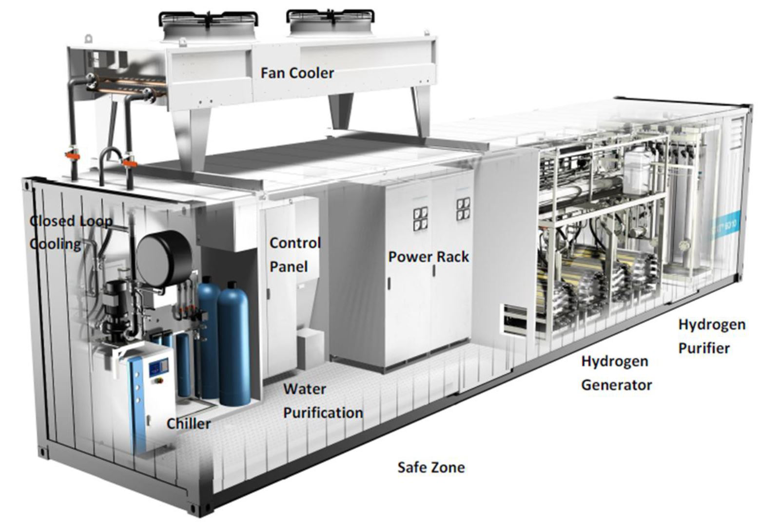
Figure 1. Inside of an alkaline electrolyser with its BoP
The purified water reaches the stack membrane of the electrolyser by a small pumping device. To perform the electrolysis on the stack membrane, it is required to apply a DC current to the electrolyser at current densities within the range of 0,5-1 A/cm2 electrode. Whether the source of this electricity comes from the grid or from on-site solar photovoltaic or wind power generation, transformers, rectifiers/inverters and other power equipment will be required to meet the electricity demand of the electrolyser. Furthermore, most of the equipment supports operating ranges from 5 to 90% of its nominal capacity, so the power management units must be able to operate within these current ranges at specified voltages by the electrolyser manufacturers.
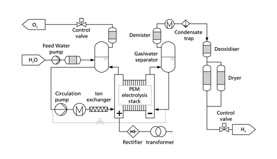
For PEM type electrolysers, it is necessary to recirculate water from the anode part of the stack (see attached diagram), that must be between 60 and 80ºC. It is important that hot distilled water is an aggressive environment and will release metal ions over time from the bipolar plates, diffusers and the stainless-steel components of the line. To prevent the accumulation of these ions in the recirculating water circuit from the anode, cartridges or tanks with “strong” cation exchange resin must be placed, as ions such as iron and titanium will be found. Depending on the size of the installation, it is possible to regenerate these resin tanks or to replace these resin cartridges and regenerate them in an auxiliary or third-party facility. Note that recirculation pumps must be capable of pumping mixed water-oxygen flows. Therefore, materials such as seals and glands must be suitable for high oxygen concentrations. Finally, a demister after the separator tank and a control valve to regulate the oxygen outflow must be included. This oxygen is vented by almost all electrolysis plants, but its value and uses must be considered.

Figure 2. BoP diagram of a PEM electrolyser
On the cathode side of the stack, besides the production of hydrogen, water is transported from the anode to the cathode. This hydrogen will therefore be saturated with steam and a water/gas separator must be installed. PEM electrolysers (and some alkaline models) allow working at an autogenous hydrogen pressure of up to 20-30 bar, which allows us to economise on the compressor. This hydrogen must be cooled to remove existing water steam and then passed through an autocatalytic converter or deoxygenator. These systems allow traces of oxygen present in the hydrogen to be eliminated through cold combustion activated by catalysts. Any water produced is removed by ion exchange resins and silica or other desiccants. Then, the hydrogen obtained is passed through a gas drying unit known as a Dryer, a preliminary step towards the end of the process involving the purification of the hydrogen obtained.
The BoP also includes analysers to measure the amount of oxygen in the hydrogen stream (OTH), and oxygen in the hydrogen produced (HTO). These parameters will be monitored in accordance with the final use of the hydrogen (industrial or mobility). Moreover, these installations include hydrogen leak detection devices, as required by the type of plant.
Lastly, the hydrogen obtained with the appropriate purity is ready to be stored and used in the desired purpose. The quality of this hydrogen is regulated by the ISO 14687-2 Standard, which refers to the limits of impurities within hydrogen that may affect the degradation of polymer electrolyte fuel cells (PEMFC) to be used, for instance, in hydrogen-powered fuel cell electric vehicles (FCEV). This standard is also aligned with the new ISO 19880-8 standard for hydrogen quality control in hydrogen refuelling stations (HRS). Another new standard that has emerged from ISO 14687-2 is ISO 21087, which covers analytical measurement procedures of hydrogen for road vehicles.
PEM vs Alkaline
PEM electrolysers coexist on the market, as well as alkaline and AEM (anionic membrane) electrolysers. The BoP of an alkaline electrolyser is quite similar to the one detailed for a PEM electrolyser but has a number of peculiarities that we will describe below.

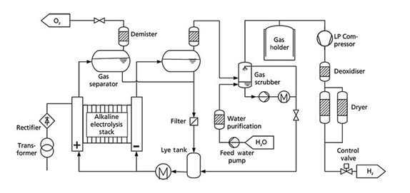
Figure 3. BoP diagram of an alkaline electrolyser
The main difference between them lies in the type of electrolyte used. While a PEM electrolyser uses water as the electrolyte, an alkaline electrolyser must use a basic solution of KOH (potassium hydroxide) or “potash lye” at concentrations of up to 30% at temperatures of 60ºC. When selecting elastomers and valve seats and other fittings, this must be taken into account to guarantee performance in such an aggressive environment. As shown in the diagram, the lye must be pumped through both the anode and the cathode and must be recirculated. Since the production of hydrogen and oxygen will consume water, it will be required to provide purified water through a washing tower to remove the alkaline mist that is generated, while monitoring the KOH concentration in the circuit.
A buffer tank and a low-pressure compressor or a blower must be installed to pump the hydrogen to the purification line, where the traces of oxygen present will be removed, as well as humidity. (This will only be needed if the outlet pressure is 10 bar, although there are 30 bar outlet pressure alkaline electrolysers on the market).
Conclusions
The aim of this article is to explain the main subsystems that comprise the BoP of the main commercial electrolysis technologies, highlighting all the operations involved in the unit. It is usual for electrolyser suppliers to include all these subsystems in their turn-key solutions. At SynerHy, we have the know-how for the selection of this equipment as well as the basic and detailed engineering to develop these projects and their successful integration.
REFERENCES