Route of a H2 molecule from an HRS to the stack of an FCEV
With this brief case study, our SynerHy team wants to describe the virtual route of a H2 molecule from its initial high-pressure (HP) compressed state in a hydrogen storage (HRS, Hydrogen Refuelling Station) to its fully decompressed arrival at the polymeric membrane in the fuel cell of any hydrogen-powered vehicle (FCEV, Fuel Cell Electric Vehicle).
To begin with, we place the molecule inside one of the Type II storage tanks of the HRS. It is compressed to 900 bar pressure from the hydraulic piston compressor. It has a very short retention time in this type of storage device. These Type II tanks are metallic (steel or aluminium) and very heavy, seamless and reinforced with an extra layer of carbon fibre or fibre glass. They can hold gases up to a pressure of 1,000 bar.
Why is it compressed to over 900 bar if the vehicle will be loaded to 700 bar here? For the molecule to enter the vehicle’s tank, it must always be at a higher pressure than the vehicle, which gives it thrust. As the molecules leave the Type II tank towards the vehicle, the remaining molecules can occupy more volume and thus the Type II tank of the HRS loses pressure. It is therefore important to ensure that the last molecule entering the tank still has the necessary thrust. This type of refuelling is called cascade refuelling.
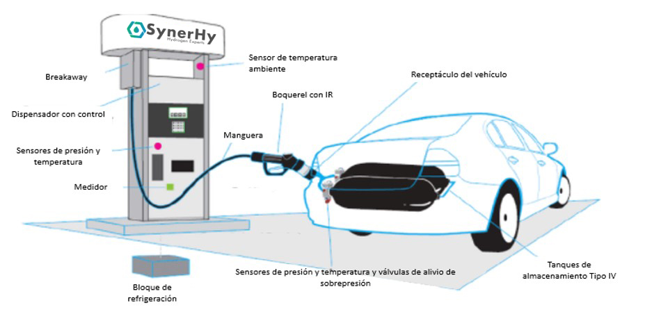
Figure 1. Main components of a hydro generator
When an HRS user unhooks the nozzle from the H2 supplier and it meets the receptacle or receiving valve of the FCEV vehicle, the molecules leave their static state at 900 bar and the FCEV recharge is begun.
The question is, who is organising and directing this first trip? We are going to focus on the controller (mass flow controller), and the communication system (IR, Infra-Red) between the hydro generator and the FCEV vehicle based on an infrared light transmitter. These are responsible for the remote control of the hydrogen refuelling operations in the HRS.
The Mass Flow Controller oversees measuring the mass flow (in g/s) and the H2 pressure as it passes through the Nozzle to the storage tank within the vehicle. It is integrated in the HRS dispenser. Before passing through the dispenser, the molecule will be cooled to the temperature of -40°C, -30°C or -20°C in the Precooling system to avoid possible overheating problems of the type IV tanks within the vehicle during the filling or refuelling process. Furthermore, the hydrogen is forced through a filter to prevent impurities before it enters the vehicle and through a so-called Check valve.
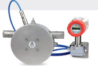
Figure 2. Coriolis type mass flowmeter
The infrared communication system exchanges relevant information between HRS and FCEV regarding hydrogen supply and storage tank temperature and pressure during FCEV refuelling operations. Having IR in the refuelling station is important, as there are vehicles that will not allow 100% refuelling if the communication is not available or is faulty. Unlike conventional petrol pumps, which measure fuel volume and have a vapour backflow cut-off, an HRS needs to monitor these parameters to know when a tank is “full”.
Once the molecule is inside the vehicle, decompressing slowly and at a very low temperature before reaching the type IV storage tank, the valve known as the On Tank Valve (OTV) is in charge of managing the entry of hydrogen into the tank. Moreover, it regulates its subsequent release, as well as the temperature and pressure at which it takes place. It is a valve that is screwed and sealed at the inlet of the storage device.
We shall now look at the parts and functions of this important valve:
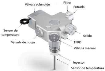
Figure 3. On Tank Valve and main components
The molecule flows into the tank through an inlet filter. For refilling, a temperature sensor attached to the nozzle is used to control the filling (bottom of the picture).
The filling is controlled by an electronic opening and closing device, a solenoid valve, which is linked to a temperature sensor to prevent overheating inside the tank. In case of overheating, the filling operation is temporarily aborted to better control it.
There are several safety devices, which can be manual or electronic. Bleed valves and temperature and pressure relief devices (TPRD). It should be mentioned that this TPRD device is not an electronic control device. It is activated when the system temperature reaches a threshold (110 °C) which causes an enclosed liquid in a glass sphere to burst resulting in the evacuation of H2 from the storage tank to the outside through an auxiliary venting system. This system is key to prevent the accumulation of pressurised hydrogen inside the tanks in case of fire or collision, avoiding the creation of a hypothetical explosive atmosphere that would produce a detonation in the environment of the FCEV.
We have already located the molecule in one of the Type IV tanks at 700 bar pressure. This type of tank is not chosen at random: unlike the Type II ones, these storage devices are very light, composed of a plastic (polyethylene) liner reinforced by a carbon fibre coating taped in an optimal pattern to withstand the stresses of high-pressure gas and a final coating of fibre glass. They are also known as Composite Tanks and are the preferred choice for automotive hydrogen pressure tanks. We are already at the beginning of the last stage of the molecule’s journey before it meets other oxygen molecules and generates electricity and water in the fuel cell membrane. We have a large amount of hydrogen compressed to 700 bar, however, how do we manage to decompress the hydrogen from 700 bar to less than 1 bar in such a small volume? This is achieved through two valves:
Pressure Regulator (PR): Like the OTV valve it has a high-pressure inlet port (HP) and a low pressure outlet (14-17 bar). This point is crucial as fuel cell membranes are extremely sensitive to overpressure and impurities, so it is necessary to ensure the optimal qualities of the incoming hydrogen using the following elements: inlet impurity filter, high- and low-pressure sensors and overpressure (PRD) and excess flow evacuation devices.
The last stage of the molecule’s path, already at low pressure (LP), is the arrival at the injector or low-pressure regulator attached to the fuel cell. The inlet pressure is slightly above 14 bar and an injection flow of 3 g/s. The outlet pressure is less than 1 bar. Based on the amount of H2 that is recirculated from the fuel cell, the amount of hydrogen injected will vary. An electronic injection device is used to inject hydrogen into the membrane according to the amount of hydrogen required. If the fuel cell does not have an injector, a second pressure regulator is required to reduce the pressure to below one bar. Commercial fuel cells are typically operating in the range of 0.3 – 0.6 bar.
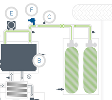
Figure 4. Simplified diagram of a powertrain of a fuel cell vehicle
In the picture, the route of the H2 from the tank to the fuel cell is shown in green. Here you can see the OTVs at the top of the tanks, the pressure regulator (C) and the injector (F).
H2 recirculation in the anode zone is done by a small recirculation pump (E). To ensure the correct operation of the fuel cell, both the air and the hydrogen being supplied must be humidified to maximise the conductivity of the membrane and therefore the efficiency of the fuel cell.
Finally, the image shows the diagram of the described route inside a truck with 6 tanks of 700 bar storage pressure. All these components found in the HRS and the vehicles are interconnected using 316L stainless steel pipes and fittings of the same material. Both pipes and fittings have to be prepared to withstand the working pressures and to prove their resistance and their physic-chemical compatibility with hydrogen at these pressures. There are specific regulations that they must fulfil, but they are mainly subjected to pressurisation and depressurisation cycles between -40 and 85°C.
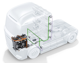
Figure 5. Component layout on a truck
In conclusion, the use of compressed hydrogen as a fuel in fuel cell vehicles requires a set of equipment to regulate the hydrogen flow in a range of temperatures and pressures to ensure the safety and the traceability of the refuelling process.
REFERENCES